
- Guides
- Posted
The PH+ guide to heat recovery ventilation
Heat recovery ventilation is an invaluable way to maintain indoor air quality in low energy buildings and minimise the loss of precious heat, but there are several issues to address to ensure optimal performance. Ventilation expert Ian Mawditt, a technical advisor on Part F of England’s building regulations, has decades of experience in field investigations of indoor air quality and ventilation effectiveness. His guide, which focuses on centralised or ducted whole house heat recovery systems, is essential reading to anyone considering such a system.
It is widely acknowledged that all buildings need to be ventilated for the health and comfort of the people inside. In low energy and, usually, more airtight buildings there is growing concern that buildings can be inadequately ventilated, leading to poor air quality inside. In the context of ventilation and health, we should consider that all new homes, built to an airtightness of below 10 m3/hr/m2@50Pa, will be reliant on purpose-provided ventilation. The problem is that many new homes have woefully inadequate ventilation provision, frequently falling short of meeting the minimum requirements of the building regulations.
This article was originally published in issue 23 of Passive House Plus magazine. Want immediate access to all back issues and exclusive extra content? Click here to subscribe for as little as €10, or click here to receive the next issue free of charge
As energy targets push the airtightness further – down to below 5 m3/hr/m2@50Pa – the health risk both to occupants and the building fabric increases if the property has insufficient ventilation provision. The standard approach to natural ventilation (e.g. trickle ventilators or holes in the wall), may not adequately maintain year-round ventilation: larger inlets/outlets would be needed, and the geometry and volume of a building would need careful design to promote natural air flow. Simply increasing the amount of trickle ventilators, may conflict with the energy performance target of the building, and may impact on the comfort conditions for occupants.
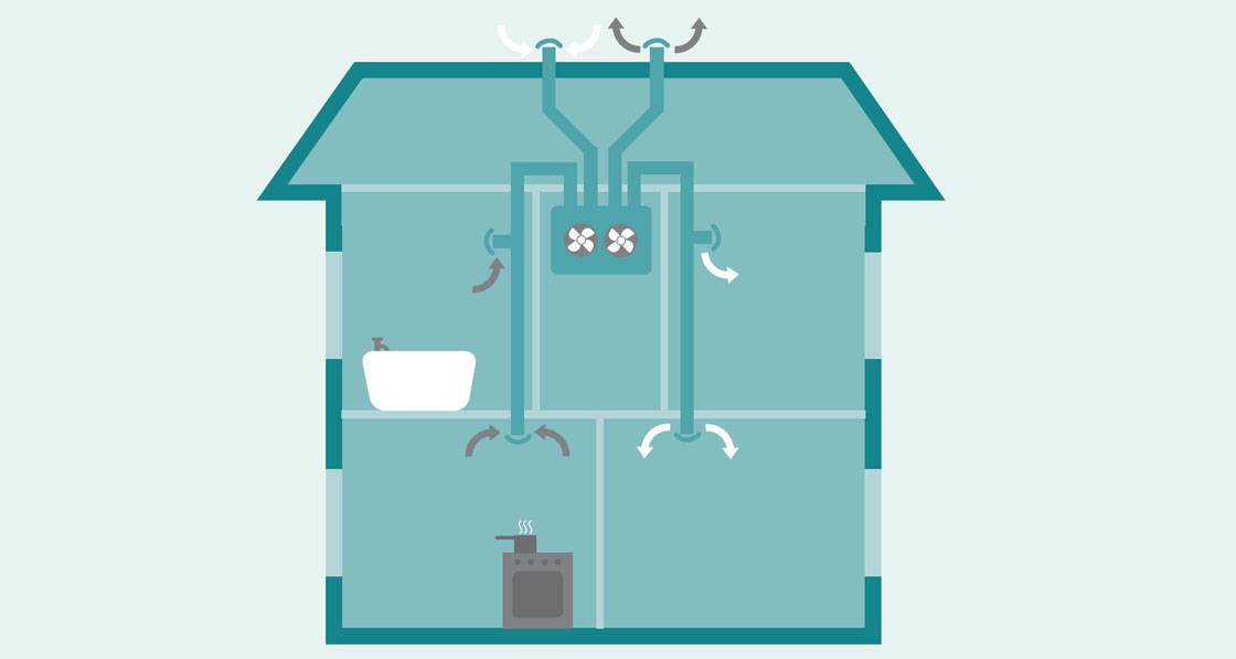
An alternative, and increasingly popular strategy to overcome this problem, is heat recovery ventilation, more commonly abbreviated to HRV or MVHR (mechanical ventilation with heat recovery). With MVHR, fans mechanically supply air into the building, and extract the stale air on a continuous basis. Both the supply and extract fans ventilate at an equal rate meaning that the air coming into and out of the building is balanced. As the incoming fresh air from outside is passed via a heat exchanger, most of the heat energy is transferred from the extract air into the incoming air stream.
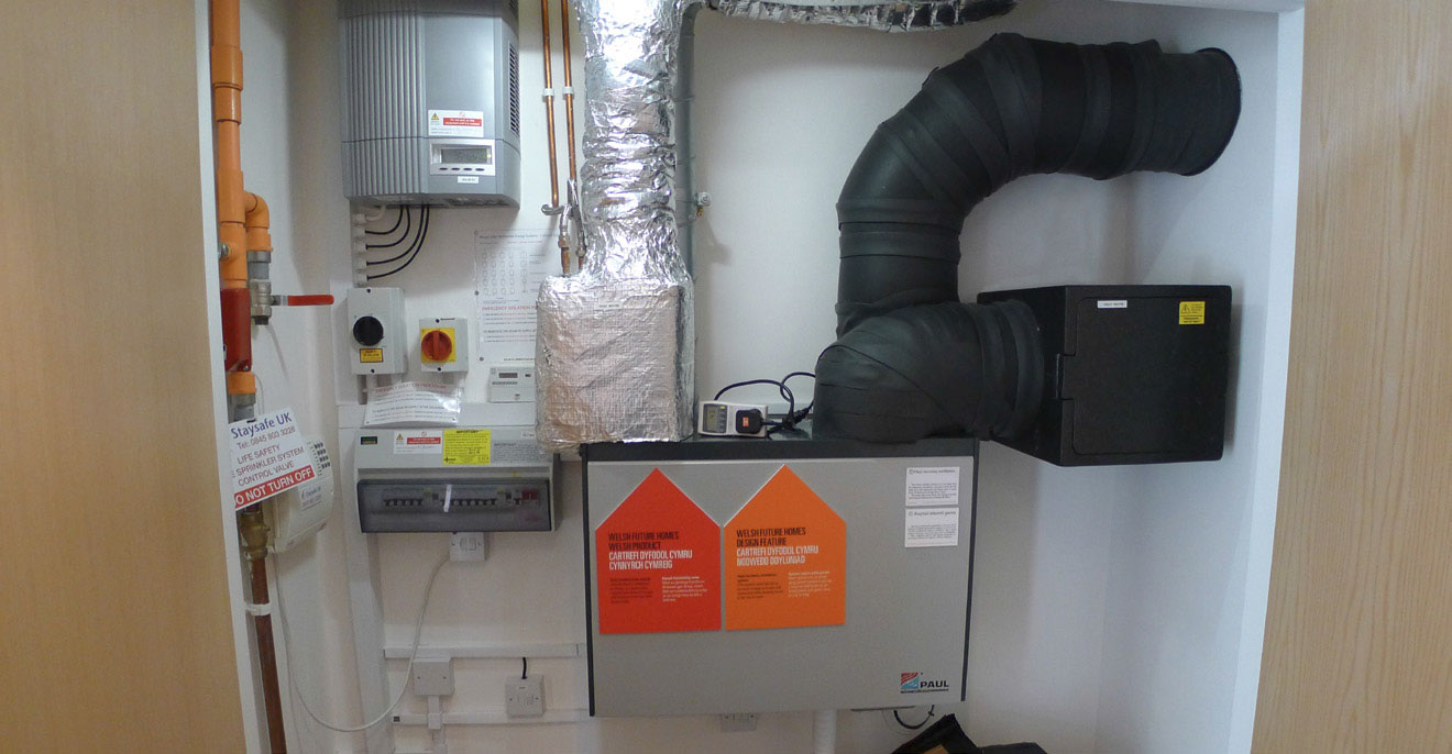
Neat and tidy installation of a Paul heat recovery ventilation system and associated equipment in Larch House, a Bere: Architects-designed passive house. Photo by Alan Clarke.
By doing this, the supply air temperature is significantly increased above the outdoor temperature, thereby reducing the risk of discomfort, and minimising ventilation heat loss. It’s probably no big surprise that passive houses, in cold and moderate climates, require an MVHR strategy to ensure the thermal comfort criteria is met year-round (e.g. fresh air supply must be no lower than 16C). The MVHR market is not limited to the passive house market either: many new-build non-passive house and (non-Enerphit) retrofit homes are using MVHR too, which, in theory is no bad thing. Correctly designed, installed, and commissioned, MVHR systems should provide and maintain good indoor air quality for many years. However, they require more forethought, otherwise they can go wrong, and be a cause for complaints. This article aims to highlight some of the key design and installation considerations to help ensure a successful installation.
Fit for purpose
MVHR systems can only help to maintain comfort conditions if they are fitted in an airtight property. The reason for this is to ensure that as much air as possible, into and out of the building, goes through the heat exchanger. Otherwise what’s the point of it?
Heat exchangers in MVHR systems should recover sufficient amounts of heat from the extracted air to make their specification worthwhile in terms of comfort, but also investment. This is known as heat recovery efficiency and is normally stated for almost all systems on today’s market, with an increasing amount of them bearing the Passive House Institute certification logo. This means that they have undergone additional tests to confirm that they meet, amongst other things, the minimum heat recovery efficiency requirement of 75%.
In fact, many systems today cite recovery efficiency of over 90%. But be careful. Just because the unit states these impressive efficiencies doesn’t mean that is what you are going to get. The efficiency of an installed system is a function of the heat exchanger efficiency, the airtightness of both the building envelope and the MVHR system (including ducting), and the correct system air flow setting and balance at commissioning.
However efficiency is also affected by the environment in which the system is installed, and therefore the MVHR unit, and all the distribution ducting connected to it (on the warm-side of the heat exchanger), should be installed within the thermal envelope of the building.
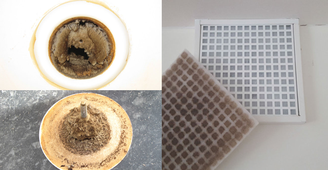
(top left and bottom) Examples of heavily contaminated kitchen extract using a valve-type terminal; (right photo) Best practice using an extract terminal with a filter cassette
On the subject of airtightness, there is often debate about how airtight an envelope needs to be. In passive houses, this is less of an issue as being very airtight (<0.6ach@50Pa) is a requirement of certification.
But, elsewhere, air permeability targets vary significantly: for instance, new dwellings in the UK are required to have a maximum permeability of 10 m3/hr/ m2@50Pa (a different unit to ach@50Pa, but for simplicity here we will assume it’s the same) if tested. In reality, the design air permeability value can be significantly below this, and is dictated by the values used in the dwelling’s SAP (or DEAP) calculation for CO2 emissions. The final tested value depends on construction type, specification, and build quality. The MVHR supply chain is often not particularly explicit about the airtightness of the properties their products are intended for, after all they do not wish to limit their market reach, and few customers are likely to measure the efficiency to challenge it. Some building designers will say, if the envelope has an airtightness of 5.0 m3/hr/m2@50Pa or below, then MVHR will be fine. But, if you want to ensure the best performance of the heat recovery, an air permeability below 3 is essential.
Not only should MVHR systems exchange thermal energy as efficiently as possible, they should also be efficient to run. As such, a further criterion for passive house systems is that they have a specific fan power (SFP) of no more than 0.45 Wh/m3, i.e. for every cubic metre of air it exchanges per hour, it should use no more than 45 Watts of electrical energy. You will find many systems on the market now have much better SFP, often below 0.25 Wh/m2. But, as with heat recovery efficiency, the actual SFP of a system will depend on the volume air flow, fan performance characteristics, and the total pressure of the connected ducting.
For these reasons, and how the systems are controlled, electrical energy consumption throughout the year between systems will vary significantly. As a rough guide, the typical annual electrical energy costs for a well-designed and installed, medium-sized unit used year-round should be in the order of £40-50/yr.
Year-round operation
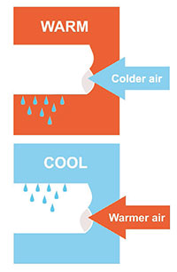
It may seem obvious that ventilation in buildings is a continuous year-round requirement. So, whilst the efficient operation of a ventilation system is important, it is of even greater importance that it is capable of operation all through the year. Many systems incorporate a summer by-pass facility, such that heat is rejected rather than recovered during warmer periods. But be careful, some cheaper systems simply switch off the supply fan, changing the system into an extract only system. This means that you may need to open windows to get air into the building in summer.
In winter, when windows will most likely be closed, we need to ensure the system is capable of uninterrupted operation. Yet, many MVHR systems on the market are not capable of year-round operation on their own, and will automatically shut down to protect the heat exchanger when the external temperature approaches freezing.
This is because the condensation forming on the heat exchanger could be excessive during these conditions, with a further risk that the cold side of the exchanger will freeze, thereby damaging the unit. But, this shutdown could happen at a time when occupant health and comfort is most reliant on good air flow through the system.
Designers will need to account for these functional limitations: selecting a unit based upon its volume flow rate capacity is simply not good enough. Ancillary equipment, such as a pre-heater on the incoming air stream is a must where this is not integral to the MVHR unit.
Accomodation & access considerations
MVHR units, their ancillary equipment, and the system ducting can all take up a significant amount of space. In addition to pre-heaters, passive house ancillaries may include a post heater in the supply air distribution for the primary heating for the property. It is imperative that house designers plan for accommodating this equipment in such a way that will encourage the long-term, successful operation of the system, which includes the ease of access for maintenance. If from the outset, the decision is to stick the unit in a loft (particularly a cold one) then think again. Most MVHR system failures relate to poor access, as awkward locations mean that they are difficult to install and commission correctly. And, if access for regular filter changes is too difficult then they also are unlikely to be changed.
Filters
Filter maintenance is a frequent topic with MVHR systems. The primary function of the filters is to protect the system and heat exchanger from dust and particulate matter clogging it up. As a secondary function, this filtration may be of benefit to the occupants, by reducing the number of particulates in the indoor air entering from outside.
There is mounting evidence to indicate that occupants living in MVHR-ventilated homes have experienced respiratory-related health improvements. Whilst much of these health improvements are likely due to improved overall ventilation rates, the presence of filters (and the increased airtightness of the building) are likely to have a role, although further research is needed to confirm this.
Different grades of filter are available: general and fine. Fine grade filters, e.g. F7 type for fine particulates, should be used (as required for passive houses) if a greater degree of filtration is desirable. General filters, e.g. G4 for coarse particulates, are normally sufficient for protecting the system. It should be remembered that, the finer the filter, the greater the resistance on the system, and the more regular the maintenance may need to be. If filter maintenance is not routine, then the performance of the system will soon be compromised. Subject to location, you will need to plan for at least twice annual changing, or every quarter. If this degree of maintenance cannot be factored in then MVHR may not be an appropriate strategy for your project. This is often debated in the context of social and private rental properties where programmed maintenance is usually limited to annual gas safe checks. It is also worth pointing out that costs for filter replacement, per year, can be greater than the electrical running costs of the system. A final note on filters: most installations that I see tend to use extract air valves throughout the wet rooms in the house, including the kitchen. However, if we want to protect the ducting and the heat exchanger with filters in the machine, why not extend this principle to the kitchen? Grease from cooking can enter the ducting and make it easier for dust and other contaminants to cling to it and compromise the performance of system. It is always best to use a filtered extract terminal in the kitchen, which usually employ a simple (cheap) fleece filter to prevent kitchen grease entering the ducting system.
Air distribution
MVHR systems usually distribute air to and from the occupied areas of the building via a network of ducts that terminate in ceiling or wall mounted grilles or valves. This system of ducting, plus the terminals and the filters, will add a certain amount of pressure at any given flow rate. There are a few terms for this, including: total pressure; system pressure; external pressure; static pressure (albeit incorrectly used here); and system resistance. Whenever I talk about the relationship between volume air flow and the resulting pressure to students, I quickly see them glazing over!
The reality is that we understood these basic physics when we were young children. Anyone who has ever had a fruity or ice slush milkshake will remember that, when a large bit of fruit pulp or slush enters the straw, the pressure in the straw increases, and you needed to apply more power (suck harder and turn pink) to increase the flow rate of the milkshake - especially if you use a bendy straw! It is exactly the same principle with ventilation ducting systems: the greater the system pressure, the greater the fan power to move the required volume of air. In any ventilation system, but especially so for MVHR (which tends to have the greatest amount of system ducting compared to other types), it is imperative that the system pressure is calculated when designing the ductwork for both the intake air/supply air side and the exhaust air/extract air side.
Otherwise, you will not be able to select the right capacity MVHR unit to deliver the air flow that you need.
Ducting is usually the weakest link in any ventilation system, and is often the primary cause of poor performance. But with a little forethought, it isn’t difficult to get right. It takes on many forms, but selecting the right design, size and type will be central to the success of the system. Further information about ducting types is given in the boxout section.
Ducting types
Ducting comes in many forms: steel, aluminium, plastic; rigid, semi-rigid, and flexible; round, rectangular, oval, and so on. The wide range of choices may seem overwhelming. Let’s get one thing out of the way first: do not use flexible ducting under any circumstances. If you really need flexibility, then use semirigid ducting with smooth internal surfaces, and only use gentle bends. Avoid rectangular ducting if possible, particularly for supply air where the duct is under positive pressure: the air flow characteristics under this condition are much better with circular or oval ducting. The choice of material mostly comes down to project budget. Rigid steel ducting is the most robust, and therefore, easier to clean. It should also last for a long time (30+ years), but this added benefit will increase the initial capital outlay. Whether metal or plastic, always use proprietary connectors, bends, tee pieces, etc. Make sure all connections have an airtight seal, and are mechanically connected. And always use ducting where the air flow performance data is available: avoid “bespoke” ducting.
There are two main ducting configurations to choose from for the air distribution to and from each room: the branch and radial systems. With the branch system, the main branches reduce as each room branches off. Radial systems are increasingly common, where the main supply and extract ducts from the MVHR unit terminate in plenum boxes from which, each room is ducted separately.
There are advantages and disadvantages with each type, although some MVHR suppliers are now beginning to widely promote the radial system. However, there are a few things to consider before settling on the most appropriate solution – any one approach may not suit every installation. Also, there is nothing wrong with a hybrid approach: anything is possible provided it is properly designed, and can be accommodated within the building.
Some key points to consider for each type.
For branch:
- This approach has lower turbulent characteristics as branches are engineered to allow smoother air flow, compared with plenum systems;
- Branch systems require greater amounts of larger diameter ducting, minimum 100mm diameter, with the main branch up to around 160mm diameter, which may cause accommodation problems, particularly when run through intermediate floors;
- Balancing of the air flow in the rooms via adjusting room valve grilles relies on good duct design to ensure local velocity (hence noise) is not too high for the required flow rate;
- Additional sound attenuation may be necessary, particularly for metal ducting;
- With branch systems there are likely to be more ducting connections, bends, and tees (compared with semi-rigid, radial), and possibly higher risk of air leakage, depending upon ducting quality.
For radial
- These systems can be easier to install as radial ducts between plenum (or manifold) and the room allow for smaller diameter (typically 75mm), and are more forgiving to the use of semirigid ducts. However, higher flow rate rooms (e.g. kitchens and large rooms) may require two radial duct runs to each terminal grille;
- Less sound attenuation is needed: cross-talk silencers can be omitted;
- A potential downside is that you need to find additional space for the supply and extract plenum boxes. These should be placed centrally in the property (not the loft, unless single storey) to minimise radial lengths;
- Use good quality plenum boxes, as poor designs can cause significant air leakage;
- Radial systems can be fiddly to commission as each radial run needs adjustment via supplied flow restrictors or dampers, and can take a while to set up correctly.
It is important that ducts are insulated – where necessary – to minimise heat losses through the system, and to reduce risk of condensation. Assuming the MVHR unit is installed inside the thermal envelope, then the intake and exhaust ducts on the cold side of the heat exchanger will need to be insulated. Condensation occurrence on these ducts will be on the outside of the duct, so insulation must be vapour resistant. Distribution ducts on the warm side of the heat exchanger do not necessarily need insulating, unless: a) they pass through an unheated area (e.g. a cold loft), in which case they need to be fully insulated to prevent condensation occurrence, which will occur on the inside of the duct (insulation need not be vapour resistant, although it is still good practice), or: b) the supply air distribution includes postheating, (e.g. some passive houses) where vapour resistant insulation would be required.
To ensure good air distribution in each room, it is important both to select, and to locate air distribution valves correctly. Get this crucial bit wrong, and you may end up with poor air circulation in rooms, or air velocity discomfort. It is always important to check the air distribution characteristics when specifying air distribution products.
But as a general principle, ceiling mounted supply air diffuser valves are best placed central to the room, as this gives greatest flexibility for floor layouts. For example, a bed in a bedroom is rarely in the centre of the room, and you should always aim to avoid air distribution directly over a bedhead. Make sure that, if you have no other option than to locate a supply valve near to a wall or corner, you fit blanking sections inside the valve (nearest the wall) to minimise the potential for vertical air velocity discomfort down the wall.
Extract air valves in wet rooms should ideally be placed on the ceiling, but if you need to wall mount, you should aim to mount the valve within 400mm from the ceiling to maximise the efficacy of moisture removal. In addition to room valves, the pathway between supply and extract air flows needs to be included in any design.
Most commonly, MVHR systems rely on the “cascade effect”, to ventilate circulation areas. This is where air moves from supply to extract points through the building, thus avoiding the need, usually, for supply air points in hallways, landings, etc. To do this air transfer between all ventilated rooms is essential, and this is normally done by providing a 10mm undercut beneath internal doors, although the exact amount can be calculated according to the designed air transfer rates.
System capacity
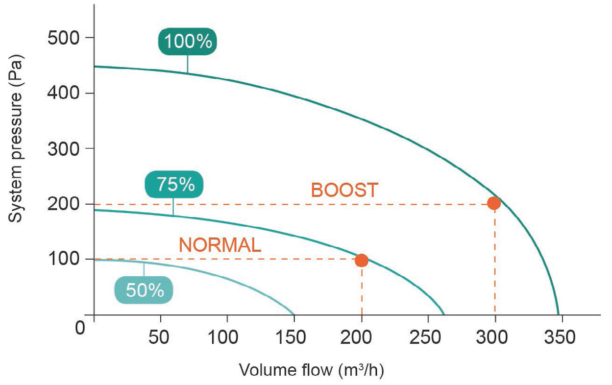
The chart shows an example of the fan performance characteristics, or fan curves, for a typical MVHR unit. It is imperative that the chart specific to the unit proposed for a project is closely examined to ensure fitness for purpose for meeting designed flow rates. You will now see why it essential to have access to the designed system pressure: you will not be able to select the right sized unit otherwise.
In theory, the unit in this example has the capacity to move some 350 cubic metres per hour (m3/h) at 0 Pa system pressure (i.e. zero resistance – isolated from a duct system) whilst operating at 100% maximum speed setting. However, depending on the duct design, system pressure could be between 50 and 150 Pa under normal operation.
Assuming 100 Pa, and a normal operation flow rate of 200 m3/h, the chart shows that the system will be operating at around 75% of its capacity. The higher setting for boost at 300 m3/h could increase the system pressure to around 200 Pa, but now the fans are operating around 95% capacity. Now there’s nothing particularly “wrong” with selecting this unit for this situation – it meets the capacity needs. But this capacity is based upon meeting minimum design requirements (i.e. complying with Building Regulations). In reality, this capacity may underestimate the real needs of the building. For example, how much influence will the number of occupants, occupant density, activity, and moisture generation have on the ventilation needs?
The point here, is never aim a design just to meet the minimum volume flow, as you may not have extra capacity should it be required. It is also important to recognise that the closer to the maximum curve you get, the more electrical energy the system will need to meet the design performance. Good practice would be to select a unit that has greater capacity, and, this is my rule, where the normal (lower speed) design flow rates can be met by no more than 60% of the available capacity, and high (or boost) design setting is met by no more than 80% of the capacity.
When sizing and selecting a unit, it is also important to consider fan control. Many lower-to-mid priced units simply run the variable speed fans at the setting selected during commissioning. However, it won’t take long for the motor bearings to bed-in, and filters to become increasingly soiled, which will progressively reduce the air flow. It is best to specify systems that have constant volume flow control, such that the fans automatically regulate the fan speeds to maintain the commissioned volume air flow when the system pressure increases. If you specify a system without this degree of control then you will need to make sure that you have greater capacity from the outset. The system will need to be commissioned at flow rates above the design values to factor the potential for reduced performance.
System noise
Noise potential can be very significant and is often overlooked during the design and installation phases. Noise is the number one reason many poor-performing systems are switched off by disgruntled occupants! Good design practice would be to locate MVHR units away from sleeping areas: another reason not to stick the units in the loft. It is best to avoid cupboards leading off bedrooms too – another common location. Noise can be minimised by sizing a larger system to operate at lower speed, thereby reducing the motor noise.
But noise relating to MVHR systems isn’t just about mechanical fan noise. “Whistle” noise due to localised air velocity is a significant cause for noise complaints, and this can be associated either with: poor design of ducting (under-sized); poor installation (e.g. sharp edges and bends); or poor commissioning (e.g. incorrect valve settings in rooms). Good ducting design will usually include sound attenuation to reduce system noise, and, if a branch system passes ducting runs between rooms then – especially for metal ducting – you may need attenuators to improve privacy.
Vibration from MVHR units can be a further nuisance, and can occur if the unit is poorly mounted, or if the ducting poorly installed. Wherever possible install a unit on a solid wall or floor and, use anti-vibration mounts (often supplied as an optional extra).

Just like with a kinked straw, MVHR systems need to apply more pressure to move air through through bendy ductwork, so it is imperative the system pressure is calculated at the outset in order to select the right capacity of MVHR system.
System commissioning and use
commissioning. The aim of the commissioning is to ensure that the system is set up correctly to deliver the design air flows as efficiently as possible, and that the intake/ supply air streams are balanced with the extract/exhaust air streams. Achieving a perfect balance in reality is not easy to do, and so as long as the imbalance is less than 10% (mandatory for passive houses) then that will be fine. Most well-designed and installed systems that I commission tend to have an imbalance of <3% when done. Commissioning any ducted system will require good knowledge of the design and installation so that limitations that might affect the commissioning process are known. This almost always means setting the fan speeds for the supply and extract fans separately to account for the different system pressures on each side. Often the supply fan will need to work harder than the extract as there tends to be more ducting and outlets on the supply side (more pressure) compared to the extract that only deals with wet rooms. Rarely have I commissioned any system and not had to change the manufacturer’s default balance settings, even if they claim to automatically balance.
The air flows – through the system and in each room – need to be measured using a calibrated volume air flow meter, so commissioning is a usually a job for a specialist. It is important to bear in mind that, since 2010, ventilation systems are a controlled service in the UK, and therefore evidence of correct commissioning of an MVHR system is notifiable under the Building Regulations (Part F for England and Wales; Part K for Northern Ireland) and should be submitted to the building control body. Evidence of final commissioning is also required for passive house certification.
MVHR systems come with some form of manual, automatic, or demand control. In many cases, occupants tend not to interact with their system too much, and, in my experience, end users will seek out the controller only if they have a problem – usually noise, air velocity discomfort, or perceived high running costs. If you do provide manual controls, then make sure they are simple to understand, and accessible (not stuck away in a cupboard). Automatic control of fans, e.g. humidity-based, should not lead to sharp increase in noise levels. The best MVHR system is one that you don’t know is there: it is quietly and efficiently ventilating the home for the comfort of the people inside. It is possible, believe me.